Modbus: Complete Guide to RTU, TCP, and Serial Communication
Last updated on 29 September 2026
The Modbus communication protocol is a widely used standard in industrial automation. This guide explains in clear language what Modbus is, which variants exist, and how to configure it practically. You will read about Modbus RTU and Modbus TCP, registers and coils, and important settings such as RS-485, baud rate, and slave ID.
Want to use Modbus data from your installation for monitoring, alarms or your own application? We help with connectivity, configuration and data processing. Discuss my integration →
What is the Modbus Communication Protocol
Modbus is a simple, open protocol developed by Modicon (now Schneider Electric) to exchange data between electronic devices. The Modbus communication protocol operates according to a master/slave model for serial lines (RTU) and a client/server model for TCP. Devices request or provide data via coils and registers with fixed addressing.
Introduced in 1979, Modbus has since grown into one of the most widely used communication protocols in the industry, with applications in PLCs, SCADA systems, energy meters, variable frequency drives, and sensors.
Why Modbus is so popular:
- Open standard: no licensing fees
- Easy to implement
- Widely supported by vendors
- Available as a serial variant (RTU/ASCII) as well as a network variant (TCP/IP)
Architecture: Master/Slave and Client/Server
With Modbus RTU, there is one master that sends commands and read requests and multiple slaves that respond. With Modbus TCP, we speak of client/server: a client (e.g., SCADA or PLC) connects with one or more servers (devices) via TCP/IP.
Data Representation: Coils and Registers
The exchange occurs via coils (1 bit) and registers (16-bit words). Coils are typically digital outputs; discrete inputs are read-only digital inputs. Input registers contain analog measurement values; holding registers are readable and writable for setpoints and parameters.
Key Characteristics
- Simple and robust — low overhead, reliable in industrial environments
- Widely supported — open standard, by many manufacturers and devices
- Master-Slave (RTU) / Client-Server (TCP) — one party controls communication
- Standardized address structure — fixed layout for coils and registers
- Flexible transport — serial lines (RS-232/RS-485) and Ethernet (TCP/IP)
- Deterministic behavior — predictable timing thanks to master-controlled polling
Supported Devices and Applications
| Application / device | Description |
|---|---|
| PLCs | Many PLCs support Modbus RTU and/or Modbus TCP for communication with peripheral equipment. |
| Sensors & actuators | Smart sensors (temperature, pressure, flow) and actuators often provide data via Modbus. |
| Variable frequency drives and motor starters | Drives use Modbus to read or write parameters. |
| Measurement and energy meters | Energy and measurement meters communicate via Modbus registers. |
| SCADA and HMI systems | Often function as master or client to collect data from Modbus slaves. |
| Gateways and converters | Convert Modbus RTU to TCP or to other protocols (e.g., MQTT). |
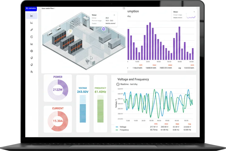
The Remote Portal from Remote is the central dashboard for managing, monitoring, and maintaining all connected installations — from one clear platform, anywhere in the world. For remote access and cloud integration, you can utilize Modbus TCP in combination with network segmentation and security measures — the Remote Portal provides full support for this.
Configuration: Modbus RTU
Modbus RTU is designed for serial communication and is suitable for simple, local networks.
Physical Connection
- Use RS-485 (most commonly used) or RS-232. RS-485 supports multidrop (multiple devices on one line).
- Ensure correct cabling and proper termination resistors to prevent reflections.
Network Parameters
- Set baud rate, data bits, parity and stop bits identically on all devices.
- Each slave receives a unique slave ID (1–247).
- Polling: the master periodically requests data; proper timing prevents collisions.
Configuration: Modbus TCP
Modbus TCP is Modbus over Ethernet via TCP/IP. The standard port is 502. A client (e.g., SCADA or PLC) connects to a server/device. For remote access and cloud integration, you can deploy Modbus TCP in combination with network segmentation and security measures.
For remote access and data logging, you can combine Modbus TCP with gateways and data loggers; pay careful attention to IP configuration (fixed IP or reliable DHCP reservation) and firewall rules.
Using Modbus TCP for remote monitoring? Discover how to directly link your installation to the Remote platform with our industrial Modbus gateways and routers.
Modbus Memory Model and Register Types
Modbus uses four register types with fixed logical addresses and function codes:
| Type | Logical address range | Description | Functions (typical) | Accessibility |
|---|---|---|---|---|
| Coils | 0xxxx | Digital outputs (1 bit) | 01 (Read), 05/15 (Write) | Read & Write |
| Discrete Inputs | 1xxxx | Digital inputs (1 bit) | 02 (Read) | Read only |
| Input Registers | 3xxxx | Analog inputs (16-bit) | 04 (Read) | Read only |
| Holding Registers | 4xxxx | Analog values / configuration parameters | 03 (Read), 06/16 (Write) | Read & Write |
Practical Examples
In Modbus messages, you use offsets starting from 0, not the logical addresses. Examples:
- Holding Register 40001 → offset 0 with function code 03.
- Holding Register 40010 → offset 9.
- Read coils: FC01; write coils: FC05 (single) or FC15 (multiple).
Coils (0xxxx)
1 bit per address, represent digital outputs. Example: 00001 = lamp on/off. Read: FC01. Write: FC05/FC15.
Discrete Inputs (1xxxx)
1 bit per address, read-only digital inputs. Read: FC02. Example: 10001 = door open/closed.
Input Registers (3xxxx)
16-bit words, read-only. Used for analog measurement values (temperature, pressure). Read: FC04. Example: 30001 = temperature °C.
Holding Registers (4xxxx)
16-bit words, read and write; for setpoint values and process data. Read: FC03. Write: FC06 (single) / FC16 (multiple). Example: 40001 = temperature setpoint.
Do you want to visualize holding registers and process data in real-time? See how we automate processes with our Modbus data monitoring systems.
Logical Addresses vs Offsets
The logical addresses (such as 40001) are intended for documentation; in Modbus messages, only the offset is transmitted. Confusion between logical addresses and offsets is a common source of errors — always check the device documentation.
Do you know exactly which register values your installation is producing right now? With the data monitoring solutions from Remote, you can read holding registers (4xxxx), input registers (3xxxx), and coils in real-time — and visualize process data in clear dashboards.
Security and Segmentation
Modbus has no built-in security. Therefore, use network segmentation (VLANs), firewalls and VPNs to protect the protocol. For broader IT/OT issues, knowledge of cybersecurity is essential in design and commissioning.
When can Remote Engineer help?
Dealing with unusual register settings, unclear readings or several devices to connect? Share the brand, model and register map. We assess the interface, addressing and required data to determine the appropriate standard configuration or custom integration. All ServiceGate routers support remote access and data logging/monitoring. Configure data logging centrally in Remote Portal; any serial interface or additional converter must match your installation.
Summary
Modbus RTU and Modbus TCP together form a robust and widely applicable standard for industrial communication. RTU is ideal for serial connections; TCP is suitable for Ethernet. The memory model with coils and registers is fixed, with holding registers being the most flexible. Understanding of offsets, function codes (e.g., FC01, FC03, FC04) and serial settings (baud rate, parity, stop bits) is essential for correct implementation.
Frequently Asked Questions (FAQ) about Modbus
From protocol to a working solution
Tell us which equipment you use and what you want to achieve. Our team assesses connectivity, configuration and any custom development. Pricing is provided in a proposal based on your application.
Also view our other supported protocols for fieldbuses and telemetry.